Parametric Plotter Drawings Part II (Now with Added Drawings!)
(This is going to be a fairly short blog post, meant more as an addition to the previous one about the plotter drawings.... aka... the drawings finally got done!)
After fiddling around with the vinyl cutter for awhile, struggling to get things centered and such, finally results:
(I also apologize in advance for the slightly crappy photo quality...)
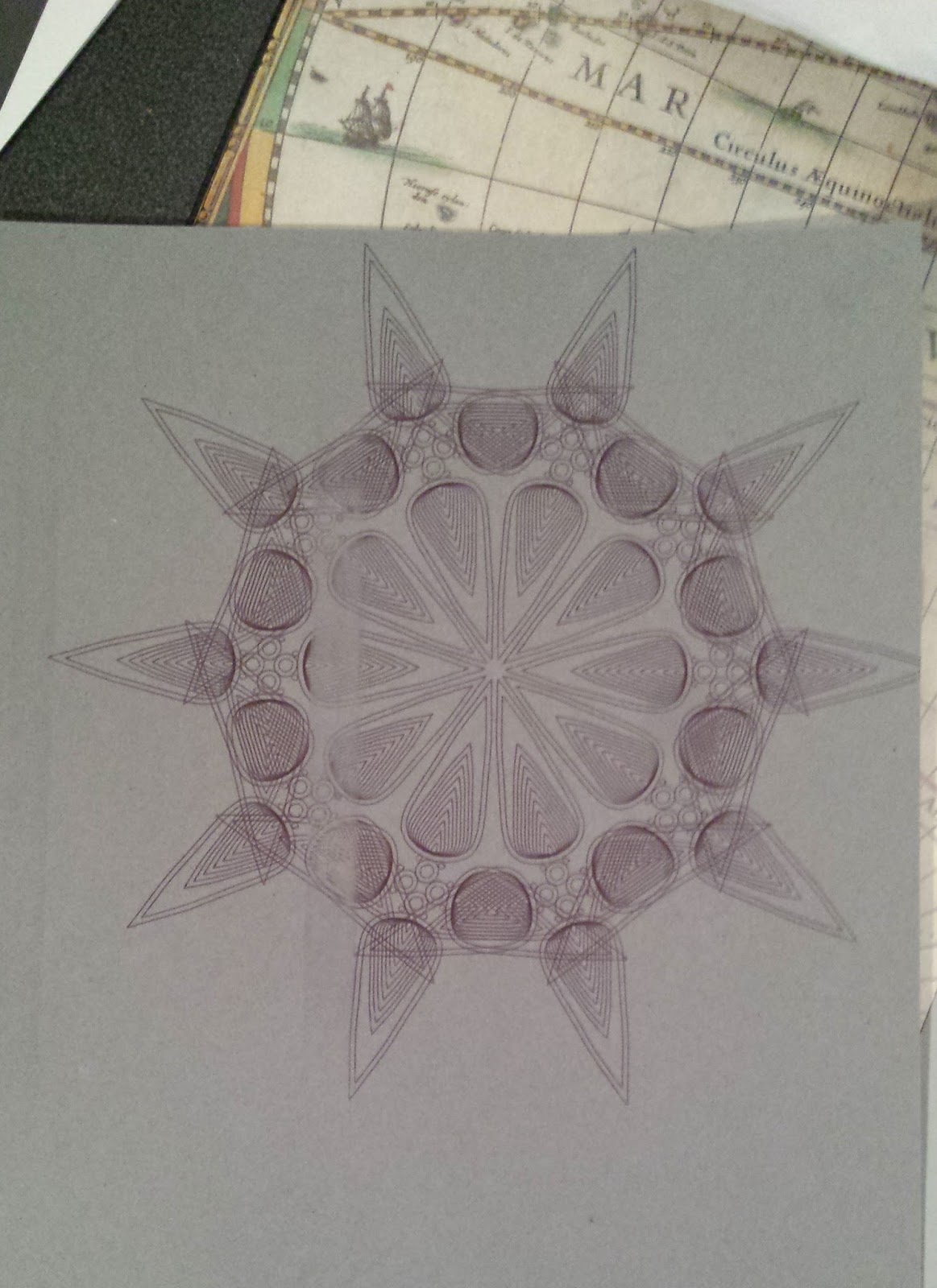
The first array I used got a little warped when I was scaling it in the vinyl cutter software.... whoops...
As the designs were fairly intricate, I used a black ball point pen on some greyish cardstock I found (under a bookshelf in my basement, of all places...).
The process of creating these arrays was pretty addicting, each little change of a slider producing a new and exciting result....
On a Random Note:
....Hmm... I wonder somewhat if it would be possible to use the vinyl cutter and a Sharpie to draw lines on a sheet of copper as... say... a resist for etching?
Or even leaving the vinyl cutter out of the equation and printing some arrays on some PnP paper... then... say... enameling the design? Bears further exploration......
......hmmmmm.......
After fiddling around with the vinyl cutter for awhile, struggling to get things centered and such, finally results:
(I also apologize in advance for the slightly crappy photo quality...)
 |
| (One of the first attempts with clear roller mark) |
A couple of them are not perfectly centered, but I got them as close as I could (I'm probably just missing some setting that would have resolved this... oh well), and on the first couple tries, one of the rollers kept picking up ink and leaving deep marks in the paper.
A couple tries later, this issue seemed to disappear (for whatever reason) and yielded some results I'm pretty happy with.
 |
| (First array, a little warped) |
The first array I used got a little warped when I was scaling it in the vinyl cutter software.... whoops...
 |
| (Second array, not quite perfectly centered) |
 |
| (Third array, in much better lighting) |
 |
| (All three arrays) |
The process of creating these arrays was pretty addicting, each little change of a slider producing a new and exciting result....
On a Random Note:
....Hmm... I wonder somewhat if it would be possible to use the vinyl cutter and a Sharpie to draw lines on a sheet of copper as... say... a resist for etching?
Or even leaving the vinyl cutter out of the equation and printing some arrays on some PnP paper... then... say... enameling the design? Bears further exploration......
......hmmmmm.......

Excellent work! To address your question.... check out this old blog post of mine:
ReplyDeletehttps://sites.google.com/site/bryanceraonline/blog-2/diycircuitboardfabrication